Microfluidics: Doing More with Less - Part 1
History, Physics, and Popular Fabrication Methods
This blog is the first in a three-part series on biological applications of microfluidic devices. This Part 1 blog will cover the history, physics, and popular fabrication methods of microfluidic devices. Part 2 will cover the application of microfluidic devices in low resource and point-of-care applications, while Part 3 will discuss the role of microfluidic devices in cutting edge technologies.

History of Microfluidics
Formally, the advent of the field of microfluidics is typically attributed to either the development of the inkjet printer nozzle by IBM in the 1950s or the development of a miniaturized gas chromatography air analyzer by a group from Stanford University in the 1970s. This development coincides with the rise of photolithography and integrated circuit (computer chip) technologies that allowed researchers to pattern complex designs at scales that were previously unimaginable. However, experiments carried out centuries earlier by English scientist and physician James Jurin (1684-1750), French physicist and physiologist Jean Léonard Marie Poiseuille (1797-1869), and German engineer Gotthilf Heinrich Ludwig Hagen (1797-1884) using tubing made from glass or brass the foundation for our understanding of the behavior of fluids at these scales. While there are many definitions, the term “microfluidics'' typically describes devices that can precisely manipulate very small volumes of liquid (nL-µL) through devices with geometries in the µm range. These factors provide microfluidic technologies with many unique advantages that have led to widespread application in many different areas such as molecular biology, energy, food science, and point-of-care applications in low resource settings. The small scale of these devices leads to many evident benefits such as low consumption of samples and reagents, low cost, rapid prototyping, reduced power consumption, and portability. However, the behavior of fluids in these small-scale devices also leads to unique physical phenomena, allowing for novel applications that could not be achieved at larger scales.

Schematics of simple microfluidics-based devices. Both take advantage of the purely laminar flow through the main microchannel. The gradient generator allows researchers to create very accurate mixtures of two solutions based on the diffusion properties of the two solutions and the geometry of the main microchannel. The H-channel filter also uses the diffusion properties of the different molecules in the sample to filter them based on size (diffusion coefficient).
What is Laminar Flow?
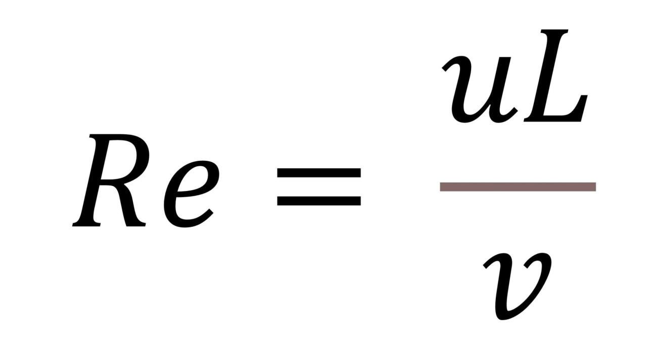
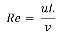
Laminar flow is a form of fluid flow characterized by an orderly flow, in which individual fluid layers (or laminae) flow parallel to each other with no fluctuations or mixing (think flow through a pipe or a slow flow through a clear stream where you can see the bottom as if the water wasn’t there). This is in contrast to turbulent flow, in which the fluid flow is chaotic with large changes in pressure and velocity (think of a large river where the bottom is obscured by the ripples and eddies caused by rapid changes in flow direction and speed). The type of fluid flow can be determined using the Reynolds number (named after Irish mathematician and physicist Osborne Reynolds, who initially described this phenomenon in 1883) and is given by the following equation:

Where v is the kinematic viscosity of the fluid (m2/s), u is the average fluid velocity (m/s), and L is the characteristic length of the channel or pipe, which for a rectangular microchannel is 4*area/perimeter (m). The transition between laminar and turbulent flow typically occurs when Re is between 2300 and 2900, with Re < 2000 indicating a laminar flow regime, and Re > 3000 indicating a turbulent flow regime. As fluid flow increases or the size of the channel increases the fluid flow tends to become more turbulent, while when the viscosity of the fluid increases the flow becomes more laminar. That is why when you pour honey (a viscous liquid) it appears to flow in a constant undisturbed line whereas if you poured water in the same manner, it would break apart into small droplets and make a mess. It is also possible to observe the transition from laminar to turbulent flow using a simple garden hose. When water initially flows out of the hose, it is traveling relatively slowly, and remains in the laminar flow regime, with the stream of water maintaining a similar diameter to that of the hose and remaining clear. As gravity begins to increase the velocity of the stream, it transitions to a turbulent flow regime becoming chaotic, breaking apart the stream into droplets and losing the glassy quality. This video provides an excellent overview of laminar flow and some great examples of laminar vs turbulent flow. At the macro scale, the transition between laminar and turbulent flow is largely dependent on fluid velocity and viscosity; however, at the microscale the size of the channels become dominant, and it becomes nearly impossible to induce a turbulent flow without external forces. For example, in a microfluidic device with a relatively large microchannel cross-sectional area of 100 um x 100 um, laminar flow can be maintained at flow rates of over 10 m/s.
The fact that the flow regime in microfluidic devices is almost entirely laminar allows researchers to create devices that would not be possible at the macroscale. One great example of this is the creation of gradient generators using “Y” or “T” junctions. In these devices, two solutions are flowed into the device and meet at a Y- or T-junction. As the flow through the microchannels are laminar, when these two solutions meet, they don’t mix like they would if you poured two solutions into a bowl, but instead flow in parallel down a single main microchannel. As these two solutions flow in parallel next to each other, mixing occurs almost entirely through diffusion (similar to how a drop of food coloring will eventually color an entire cup of water even without mixing). This allows researchers to precisely predict and control the concentrations of different diffusing molecules in the gradient generator. By varying the length of the microchannels and combining multiple gradient generators in a single device, an endless variety of arbitrary concentration gradients can be produced, and at the end, the main microchannel can be split into a series of smaller microchannels that contain a specific combination of the two solutes, or the newly formed gradient can be used directly. The H-cell filter is another microfluidic device that leverages the laminar flow regime found in microfluidic devices, and essentially operates like a gradient generator in reverse. Similarly to a gradient generator, in an H-cell filter, two solutions are flowed in parallel through a single main channel. However, in this case one stream contains a mixture of different particles to be separated (sample stream), while the second contains a simple buffer or solvent (buffer stream). As the two streams flow down the main channel, particles with larger diffusion coefficients are able to diffuse laterally from the donor stream to the receiver stream, while larger particles largely remain in the donor stream. At the end of the H-cell, the main channel is split, and the buffer stream that now contains many of higher diffusivity particles is separated from the sample stream. By varying different parameters such as the length and cross-sectional area of the main channel along with the flow rate, researchers are able to tune the separation properties of H-cells for different mixtures and experimental goals.
Fabricating Microfluidic Devices
Microfluidic devices can be fabricated from a number of different materials and methods, however the most common method used by researchers is a method called “soft lithography.” Soft lithography is a multi-step process that begins by fabricating a master mold using standard photolithographic techniques. During this step a silicon wafer is covered with a thin (µm scale) layer of photoresist. Photoresists are polymers that can be applied to silicon wafers at specific thicknesses, in which patterns can be defined upon exposure to UV light. For microfluidic devices the photoresist used is typically SU8, which is an epoxy-based photoresist that can be applied at thickness ranging from 100s of nms to 100s of µm. After the SU8 application, the design of the microfluidic devices is defined by exposing the layer of SU8 to UV light through a photomask (similar to an overhead projector transparency), which cross-links the SU8 exposed to the UV light creating a permanent structure. The remaining unexposed SU8 can then be removed by immersing the wafer in a specialized development solution.

Schematic showing the typical fabrication process for microfluidic devices.
Once the master mold is fabricated another polymer, polydimethylsiloxane (PDMS), is poured over the mold and allowed to cure, forming a replica of the master mold. The PDMS replica is then cut to size and fluid connection ports are added, and the now completed PDMS overlay along with a glass base is exposed to oxygen plasma which alters the surfaces of the PDMS and glass adding silanol (SiOH) groups. When the PDMS and glass are placed in contact with each other, these silanol groups form covalent bonds, creating a permanent bond between the PDMS and glass that is capable of withstanding the pressures used to drive flow in the microfluidic devices. This method of fabrication is popular among researchers for a number of reasons, most notably that it is relatively simple and inexpensive. The most expensive and time-consuming step is the fabrication of the master mold, which can be used 10s to 100s of times and, due to the small size of microfluidic devices, contain numerous designs. The use of PDMS also has many benefits, most notably the ability to accurately replicate patterns down to the single nm scale. PDMS is also mechanically durable, chemically inert, optically clear, biocompatible, and gas permeable. This makes PDMS based microfluidic devices amenable to many different biological applications which will be discussed in future blog posts.
References
Castillo-León, Jaime. "Microfluidics and lab-on-a-chip devices: history and challenges." In Lab-on-a-Chip Devices and Micro-Total Analysis Systems, pp. 1-15. Springer, Cham, 2015.
Fan, Jing, Shuaijun Li, Ziqian Wu, and Zi Chen. "Diffusion and mixing in microfluidic devices." In Microfluidics for Pharmaceutical Applications, pp. 79-100. William Andrew Publishing, 2019.
Gravesen, Peter, Jens Branebjerg, and O. Søndergård Jensen. "Microfluidics-a review." Journal of micromechanics and microengineering 3, no. 4 (1993): 168.
Rogers, John A., and Ralph G. Nuzzo. "Recent progress in soft lithography." Materials today 8, no. 2 (2005): 50-56.
Schulte, Thomas H., Ron L. Bardell, and Bernhard H. Weigl. "Microfluidic technologies in clinical diagnostics." Clinica Chimica Acta 321, no. 1-2 (2002): 1-10.
Yu, Miao, Tiago Castanheira Silva, Andries van Opstal, Stefan Romeijn, Hayley A. Every, Wim Jiskoot, Geert-Jan Witkamp, and Marcel Ottens. "The investigation of protein diffusion via H-cell microfluidics." Biophysical journal 116, no. 4 (2019): 595-609.
